
Explore the circuit
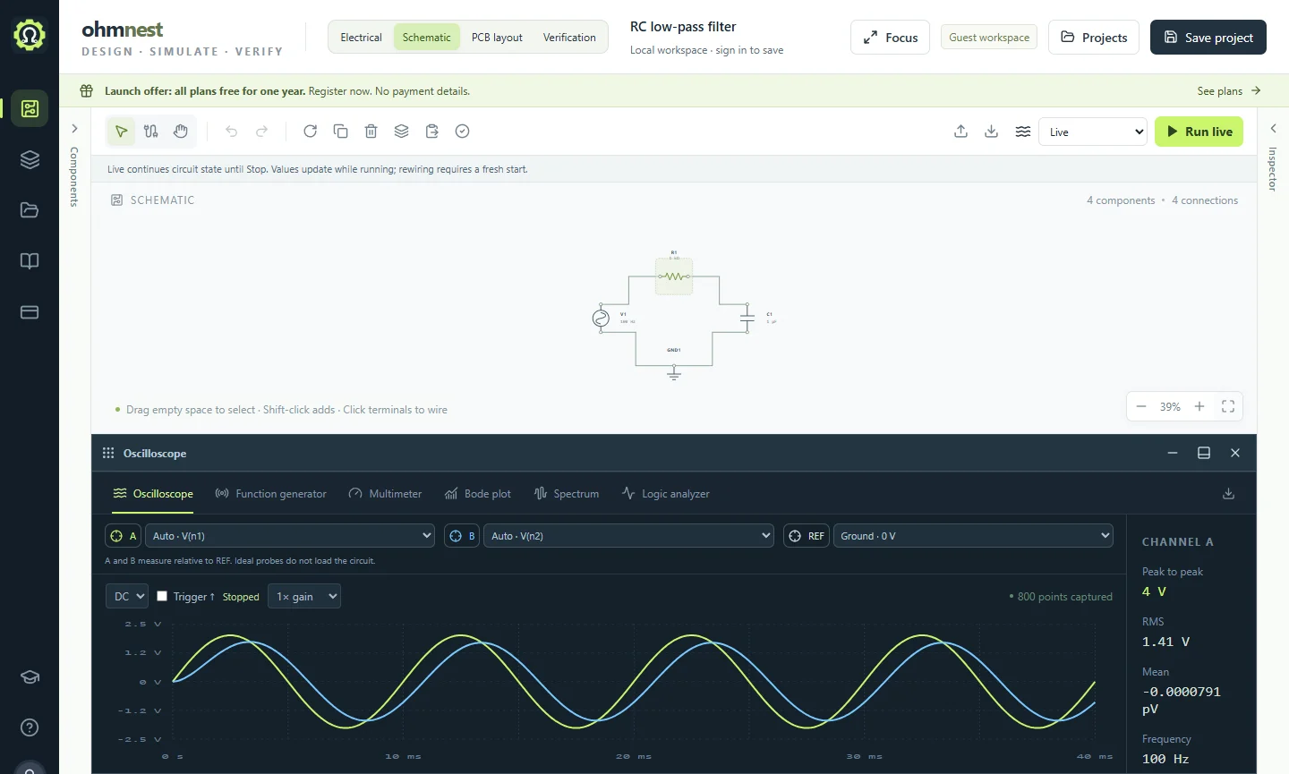
Inspect the component values and connections, then run the transient analysis. Select signals by the component terminals listed in the instruments. After changing a value, run again and compare the new result.
Calculate the cutoff frequency
This example connects a 1 kΩ resistor in series with the source and a 1 µF capacitor from the output to ground. The time constant is τ = RC = 1 ms. The cutoff is fc = 1 / (2πRC), approximately 159 Hz.
Compare three input frequencies
For this unloaded filter, the voltage gain is 1 / √(1 + (2πfRC)²) and the phase is −atan(2πfRC). V1 starts at 100 Hz with a 2 V peak sine wave. These are steady-state calculations; the first cycles can include startup effects.
| Source frequency | Output / input | Output peak | Phase lag |
|---|---|---|---|
| 10 Hz | 99.8% | 2.00 V | 3.6° |
| 100 Hz | 84.7% | 1.69 V | 32.1° |
| 1 kHz | 15.7% | 0.314 V | 81.0° |
Measure it in the workbench
- Open the demo and use Schematic. Select V1 to inspect Frequency and Amplitude.
- Open the oscilloscope. Connect channel A to V1's positive terminal, channel B to the R1–C1 junction, and REF to ground.
- Capture the default 40 ms transient. Compare the peak-to-peak voltages after startup; their ratio should be about 0.85.
- Change V1 to 1 kHz and capture again. The output should be much smaller.
- For a frequency sweep, select AC analysis and open Bode plot. Compare input and output; at the cutoff their ratio is about 0.707, or −3 dB.
Try a slower filter
Change C1 to 100 µF, V1 to 1 Hz and Duration to 1.05 s. The cutoff becomes about 1.59 Hz. The frequency-to-cutoff ratio stays the same, so the output still has about 85% of the input amplitude. Watch this configuration in the short video.
If the result looks wrong
Check that channel B is on the capacitor's upper terminal and that REF is on ground. A 1 mF capacitor is one thousand times larger than 1 µF. A load connected across C1 changes the gain, so the values above apply to the supplied unloaded circuit.
Components in this demo
| Reference | Component | Explicit parameters (SI units) |
|---|---|---|
| V1 | generator | frequency: 100 amplitude: 2 |
| R1 | resistor | Component default |
| C1 | capacitor | Component default |
| GND1 | ground | Component default |
Unspecified values come from the component library. Inspect each part in the workbench before using the model in another design.
Work through it step by step
Use the scope and function generator
Compare two signals, change a source and read time-domain measurements.
5 minutesRun a circuit live
Keep a circuit running while you adjust the generator and component values.
7 minutesRead Bode plots and spectra
Measure filter gain and phase, then inspect the frequencies in a captured signal.