
Explore the circuit
Inspect the configured study, variations and acceptance limits in the Verification workspace. Run the study, inspect its report and compare the result after changing a tolerance or device model.
Calculate the closed-loop gain
The input VIN is 100 mV DC. RF = 90 kΩ feeds the output back to the inverting input, while RG = 10 kΩ connects that input to ground. Negative feedback gives an ideal gain of 1 + RF/RG = 10, so the expected output is approximately 1 V. The amplifier has ±12 V supplies and a 100 kΩ output load.
Run the nominal circuit
- Open the example. It starts in Verification with a resistor-corner study already configured.
- Switch to Schematic and use DC operating point for a single nominal result.
- Measure U1 OUT relative to ground with the multimeter or scope channel selector. The output should be close to 1 V.
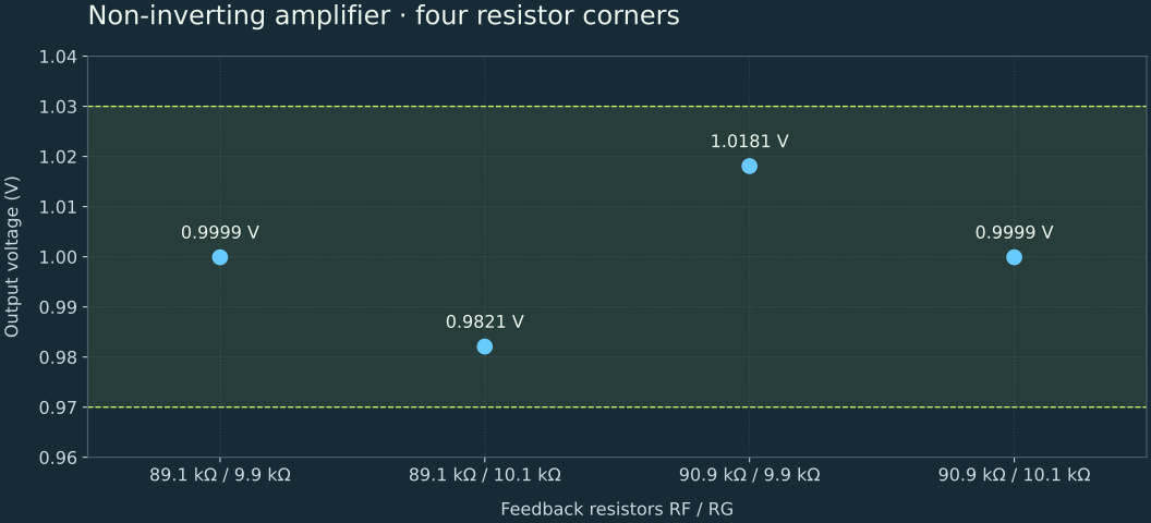
- Return to Verification and run the configured four-corner study. Its acceptance interval is 0.97–1.03 V.
What 1% resistors do to the output
These are calculated resistor corners with the input and supplies held fixed. The smallest gain occurs with RF low and RG high; the largest occurs with RF high and RG low.
| RF | RG | Ideal output |
|---|---|---|
| 89.1 kΩ | 9.9 kΩ | 1.0000 V |
| 89.1 kΩ | 10.1 kΩ | 0.9822 V |
| 90.9 kΩ | 9.9 kΩ | 1.0182 V |
| 90.9 kΩ | 10.1 kΩ | 1.0000 V |
Explore the feedback ratio
In a nominal DC capture, change RF to 40 kΩ while retaining RG = 10 kΩ. The gain becomes 5 and the output should become about 0.5 V. Update the Verification variations as well before running a new tolerance study: the original study explicitly uses resistor values around 90 kΩ.
Understand this model's limits
This is a behavioral amplifier. The demonstration has no physical bandwidth or noise model, so it cannot establish a real op-amp's frequency response, noise or stability. Supply clipping and feedback polarity still matter. An output near a supply rail is a reason to check the connections and requested gain.
Components in this demo
| Reference | Component | Explicit parameters (SI units) |
|---|---|---|
| VIN | voltage | voltage: 0.1 |
| VP | voltage | voltage: 12 |
| VN | voltage | voltage: -12 |
| U1 | opamp | Component default |
| RF | resistor | resistance: 90000 |
| RG | resistor | resistance: 10000 |
| RL | resistor | resistance: 100000 |
| GND1 | ground | Component default |
Unspecified values come from the component library. Inspect each part in the workbench before using the model in another design.
← All example circuits