
Explore the circuit
Inspect the component values and connections, then run the transient analysis. Select signals by the component terminals listed in the instruments. After changing a value, run again and compare the new result.
How this 555 oscillator works
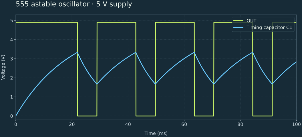
The supplied circuit uses a 5 V source, RA = 10 kΩ, RB = 10 kΩ and C1 = 1 µF. C1 charges through RA and RB, then discharges through RB. Trigger and threshold monitor C1; reset is held high. The timing voltage moves between approximately one-third and two-thirds of the supply.
Calculate frequency and duty cycle
Using the standard astable relationships: high time ≈ 0.693(RA + RB)C, low time ≈ 0.693RB C, and frequency ≈ 1.44 / ((RA + 2RB)C). Here that gives 13.86 ms high, 6.93 ms low, about 48 Hz, and a high-time duty cycle of 66.7%. See Texas Instruments' 555 datasheet, Astable Operation.
Inspect the output and timing capacitor
- Open the demo in the workbench. The default transient lasts 100 ms and starts with zero initial conditions.
- Open the scope. Connect A to U1 OUT, B to the upper terminal of C1, and REF to ground.
- Run a capture. After the first startup pulse, the output repeats about every 21 ms. C1 should cycle around 1.67–3.33 V.
- Enable the trigger on channel A to compare repeated pulses. Measure complete periods after startup.
Change one component
| Experiment | Expected frequency | High-time duty cycle |
|---|---|---|
| Original: RA = RB = 10 kΩ, C1 = 1 µF | About 48 Hz | 66.7% |
| Change C1 to 10 µF | About 4.8 Hz | 66.7% |
| Restore C1; change RB to 20 kΩ | About 28.8 Hz | 60% |
For 10 µF, increase the capture duration to 1 s so several periods fit on screen.
Why might it stay high or low?
Check the reset connection, the link between trigger and threshold, and the discharge pin's connection to RA and RB. Use transient analysis to see oscillation. The generic timer model demonstrates timing behavior; output voltage, drive current and switching details are not a substitute for a particular manufacturer's device model.
Components in this demo
| Reference | Component | Explicit parameters (SI units) |
|---|---|---|
| V1 | voltage | voltage: 5 |
| RA | resistor | resistance: 10000 |
| RB | resistor | resistance: 10000 |
| C1 | capacitor | capacitance: 0.000001 |
| C2 | capacitor | capacitance: 1e-8 |
| U1 | timer555 | Component default |
| RL | resistor | resistance: 1000 |
| GND1 | ground | Component default |
Unspecified values come from the component library. Inspect each part in the workbench before using the model in another design.
← All example circuits